PerformanceManual
Driver Controls
Reset Reference Lap
MARK button: long press
Suspension
Parameters
Springs
ARB
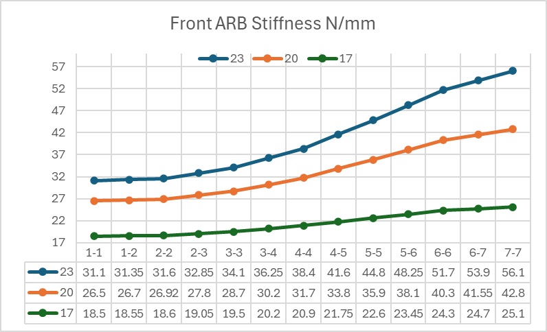
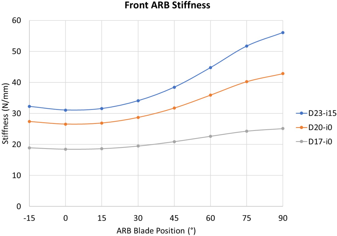
Front ARB - 17 mm - 20 mm - 23 mm
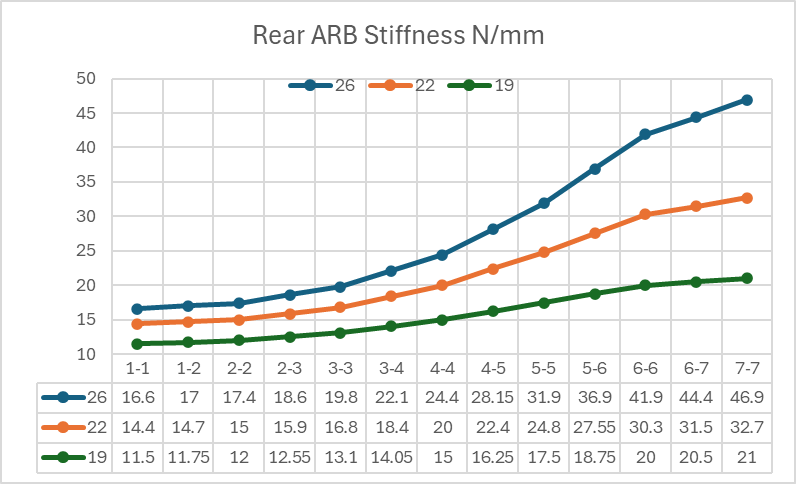
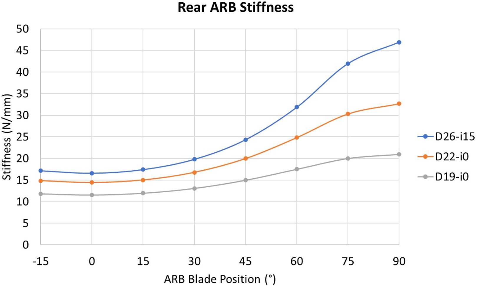
Rear ARB - 19 mm - 22 mm - 26 mm
Bump Stop
Kinematics
Graphs
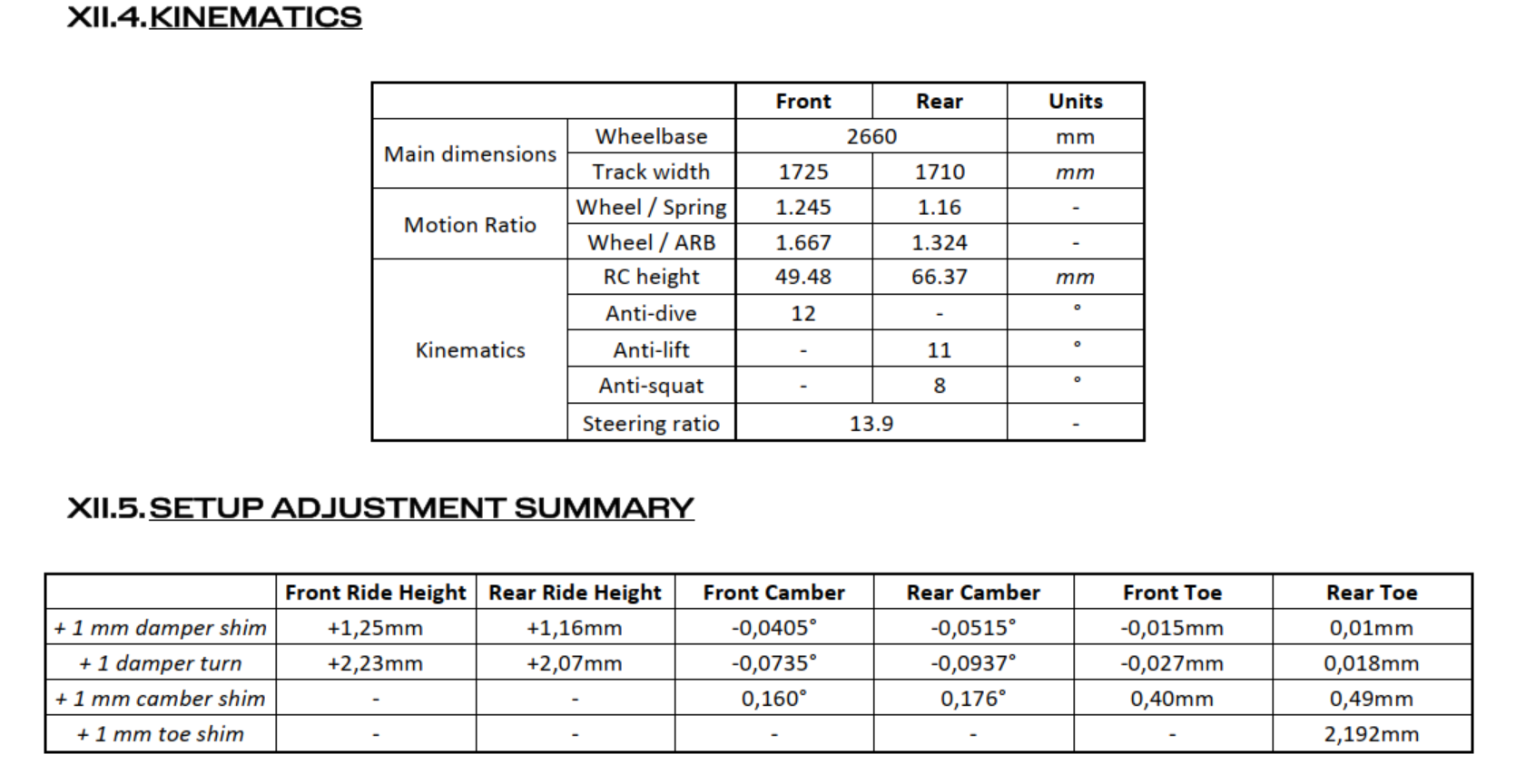
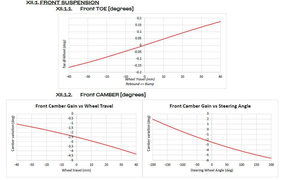
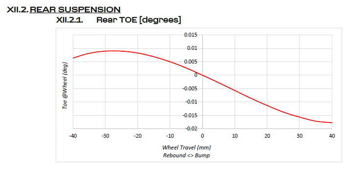
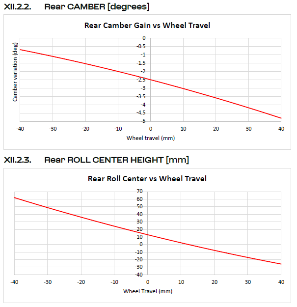
This document shows the orginal kinematics data for the Ferrari 296 from the manifacturer's manual (V3.28)
Pickup Points
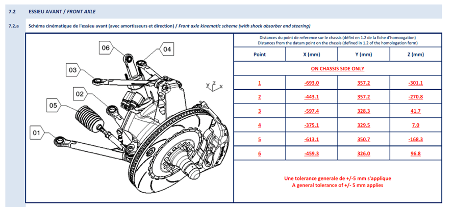
A way to change the dynamic car behavior is to change the suspension pickup point coordinates. Once the car has more anti-dive, there are fewer chassis movements, and the static ride height can be lower.
To increase the car's anti-dive, the upper and/or lower chassis pickup points (points 1, 2, 3 and 4) of the left side should be rotated clockwise.
That could be achieved by moving down the Z coordinates from points 2 and 4 and/or moving up the Z coordinates from points 1 and 3.
The side effects of altering the total car anti-dive include a reduction in mechanical grip during braking, which causes drivers to lose the feeling of grip as the car becomes stiffer.
Brakes
Temperature & Wear
Updated 23 de janeiro de 2024

Brembo
Main contact: Brandon Miller (bmiller@brembo.com, +1 714 204 8044)

- Temperature should be typically looked at as the minimum temperature EOS (end of straight) for the discs. Usually the peak temperature is not a concern since it’s for a brief moment of time
- Target EOS temperature is between 350 to 400 (or 450), for both axles. This applies to both RB340 & 210
- EOS temperatures above 550 become a concern, though the discs will be just fine doing only one stint with those temps
- EOS temperatures below 350 will give a higher mechanical wear for the pads
- Expect higher wear rates in shorter runs since the discs are still cold every time you leave the pits
- Running the discs backward would increase cooling, but need to confirm it is legal
- To get minimum wear rate, would normally want to minimize the difference between EoS and Peak temperature - naturally leads to using a disc with more thermal mass
- If want more bite, can go with an RB360. Higher friction and higher wear rate. OK for sprint racing.
- BEDDING. Suggests at least 8 laps (Daytona), but rule of thumb for BR340 is to run it until you have stable temperatures (the shape of the temp trace is constant between laps). At this point the friction will drop and should stabilize. Think about adding blanking to speed up this process to save time.
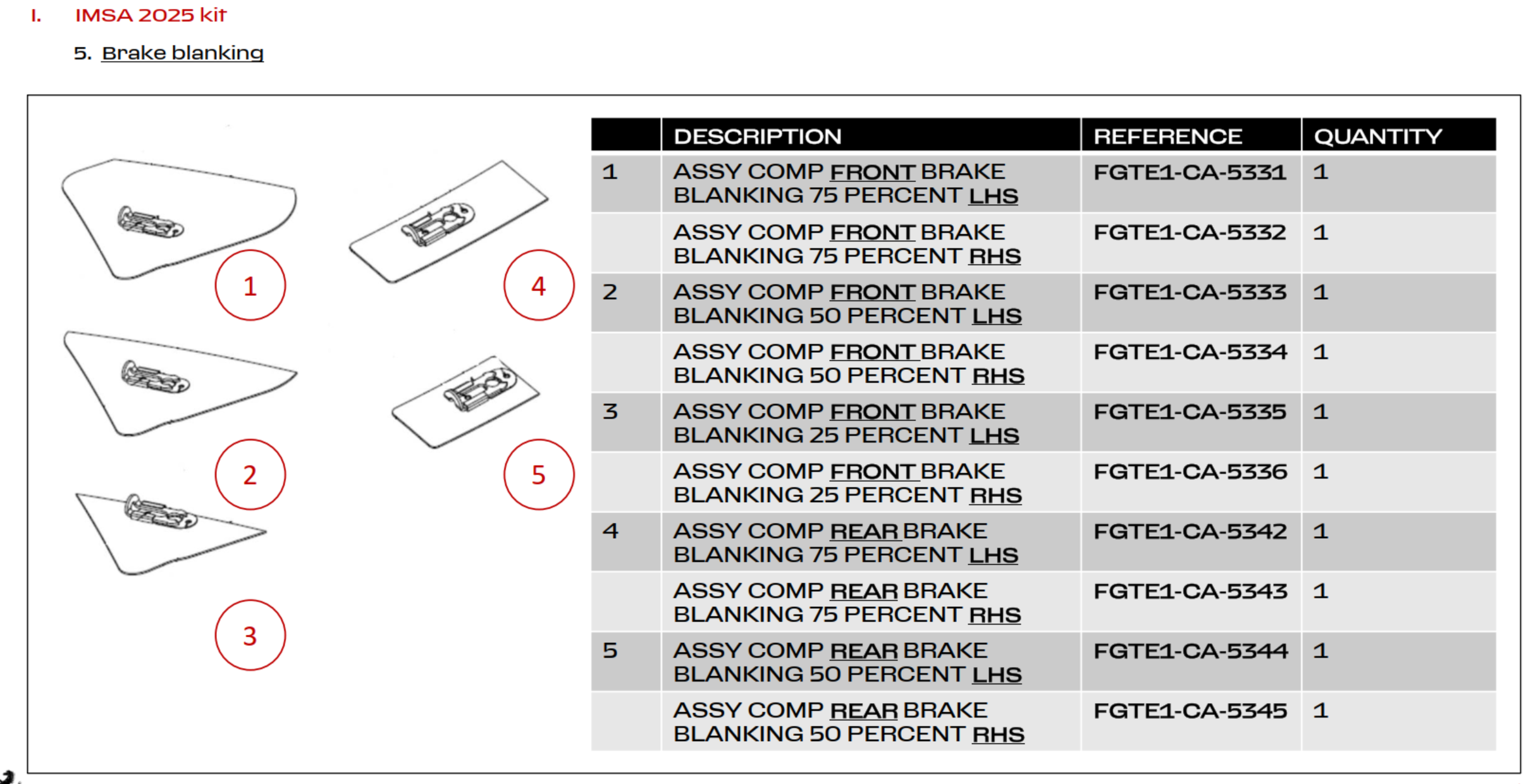
Blanking Plates
ABS
Aerodynamics
The Oreca manuals contains only one page with information about the aerobalance change. This table is showed below.
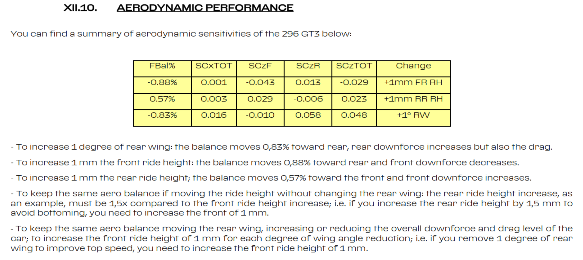
Through this information, the lower the car is, the better. However during Sebring test the car was running low as possible to not damage the floor and it was pretty unstable no matter what geometric parameters were adjusted.
Oreca's simulation tools doesn't provide a transient analysis, thus it is uncappable to describe the phenomema in limit region.
By data analysis is it possible to evaluate the reason of this brake instability on entry that the drivers complaints is some tracks.
Powertrain
Traction Control
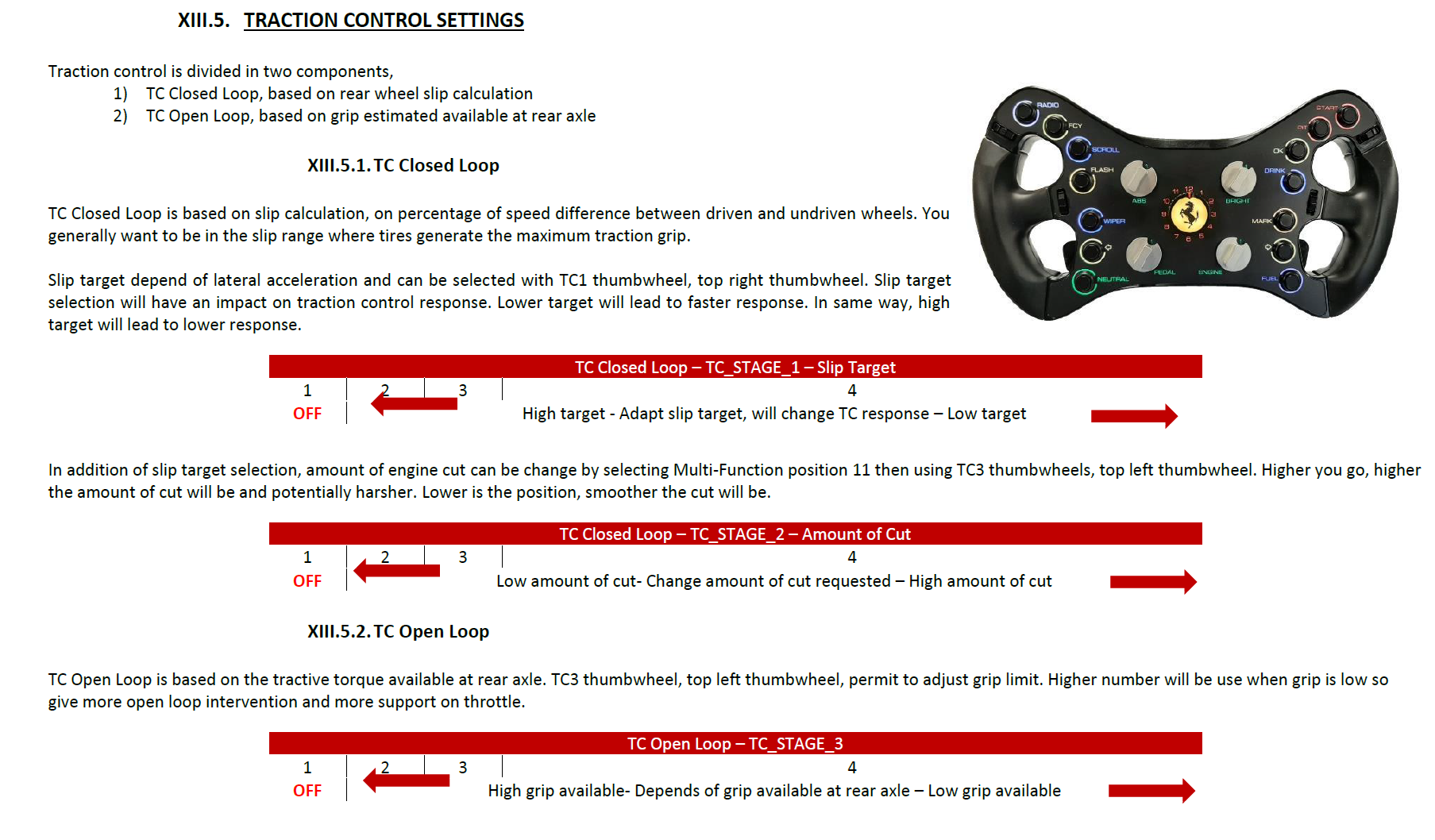
TC1 = Slip (closed loop)
TC2 = Gain (closed loop)
TC3 = Grip Level (open loop) - This is taylor made by Oreca for each track
TC Fix
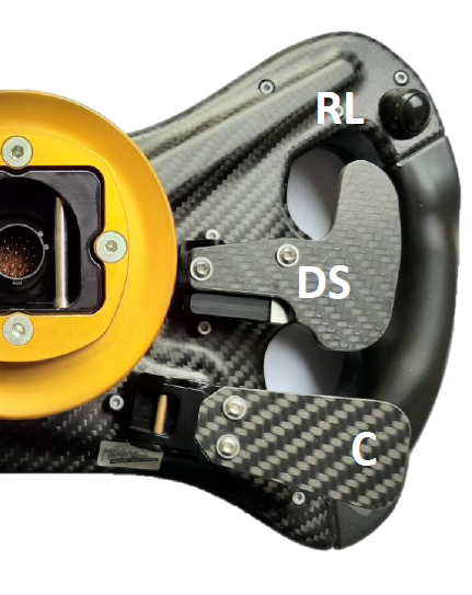
- Press left button on the back of the steering wheel. Switch TC positions on default position for 5 seconds. The default positions adjustable in RaceConn project
- A good strategy can be to have TC fix with TC1 = 2, TC2 = 2, TC3 = 1 (off). This would mean the minimal TC intervention for corners/situations where the traction is high.
Engine Brake
To select engine brake maps, move the multi-function into position 2 then use the R3 unit thumbwheels to select the position. The positions go from 1 to 6. The higher the number, the higher is the engine braking.
We tested back to back with 2 pro drivers between positions 6 and 2 and they were not able to notice a difference. It was supposed to change engine brake torque and therefore differential behavior when preload is low (in this case it was low at 25 Nm).
Power Clipping
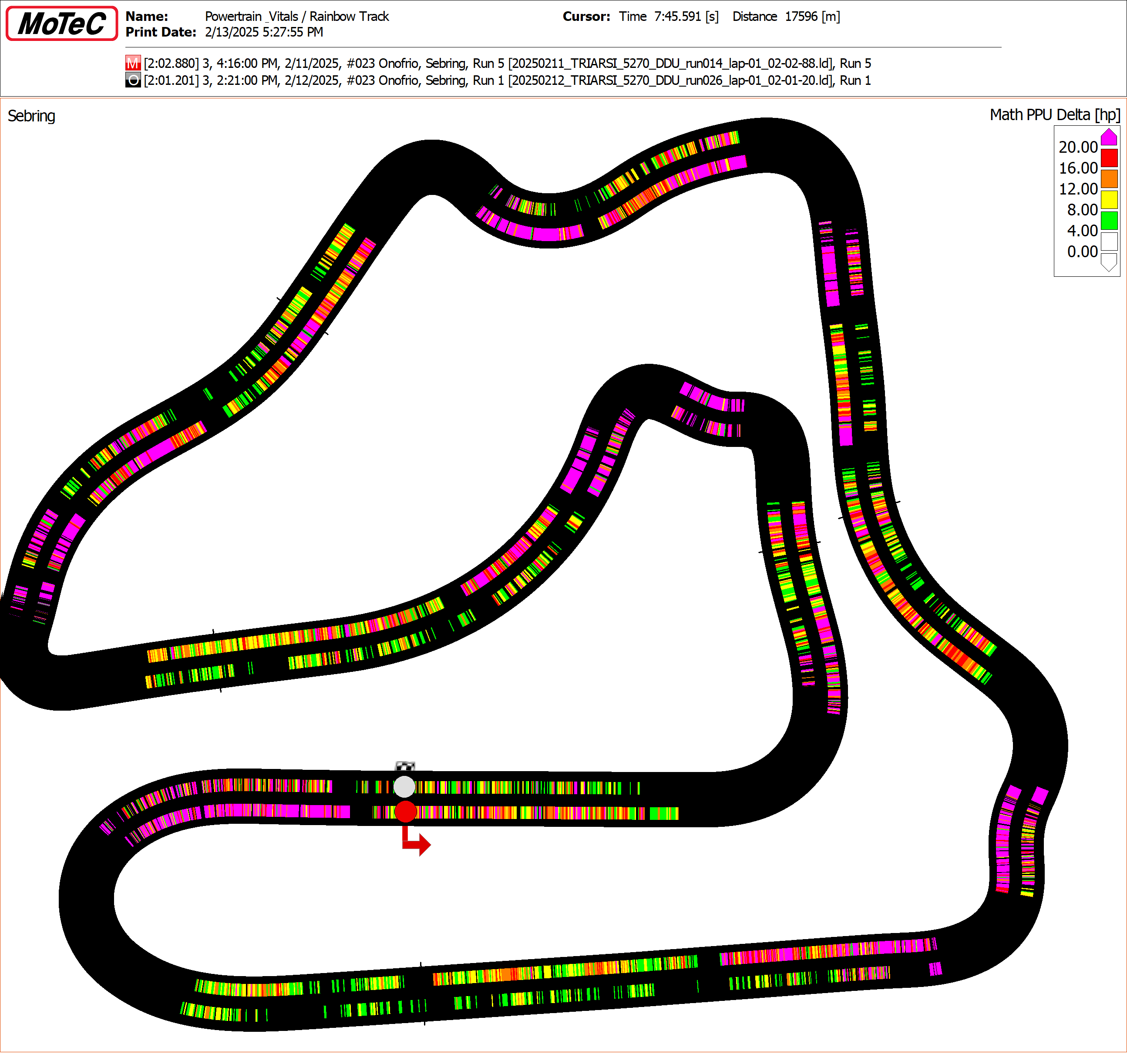
Adjust the amount of torque delivered in function of the RPM and Gear. The table is based in ratio of maximum RPM allowed by the BoP. The higher the number, the stronger will be the intervention. There are 6 levels to adjust the cut level. This adjusment change the rate that the PPU Illegal increase over bumps, especially on corner exit
Insert image with example of 2 curves
Another way to visualize with it's necessary to adjust the Clipping level is by looking the amount of wasted power on exit (pink areas). The image below shows an exameple of two differents configuration. The inner line was performed with the default Oreca's configuration (Engine Map 4, Clipping 4 and Integral 4), the outside path was made with the most powerfull adjusments (Engine Map 1, Clipping 1 and Integral 2)
Power Integral Target
Defines from what PPU Illegal level the ECU will start to intervent on the torque delivered. Ferrari's configuration allows up to 5 positions, however, only 4 positions are being used. Position 1 is restrictive as position 5. The recommend position is 4, which in actual map starts to intervert whenever the PPU Illegal is above 2 KJ. Position 3 is one step less restrictive, and starts to work above 4 KJ. While postion 2 is the less aggressive and will only intervent after exceed 5 KJ.
This parameters can be adjusted based on track distance. The project segment the track in 10 segments with equal distance, this means that the ECU is cappable of have different eletronics intevention for especific corners, however we don't know if this is allowed by IMSA. Later on the season this should be investigated.
Insert power integral constant lines
Decrease Rate of PPU Illegal
During the sweep test, the decrease rate of PPU Illegal had changed. Why this had happened? Wasn't the constant defined by the technical regulations?
Setup Changes
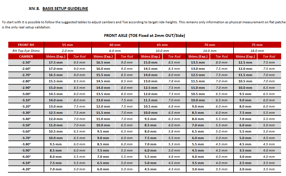
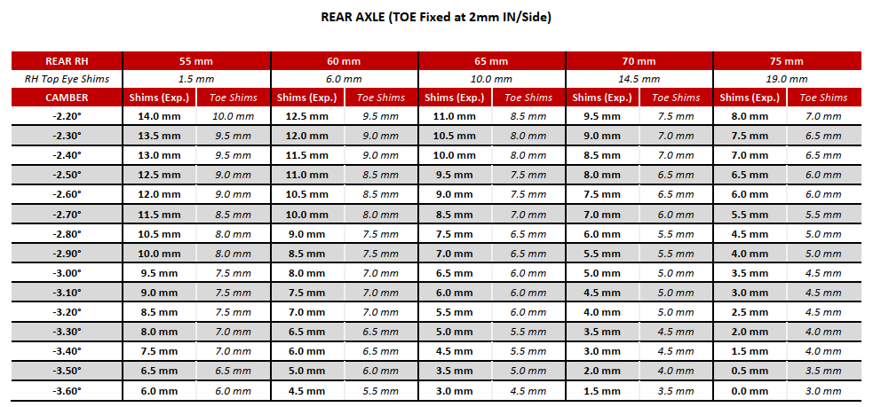
Camber Change
Front Axle
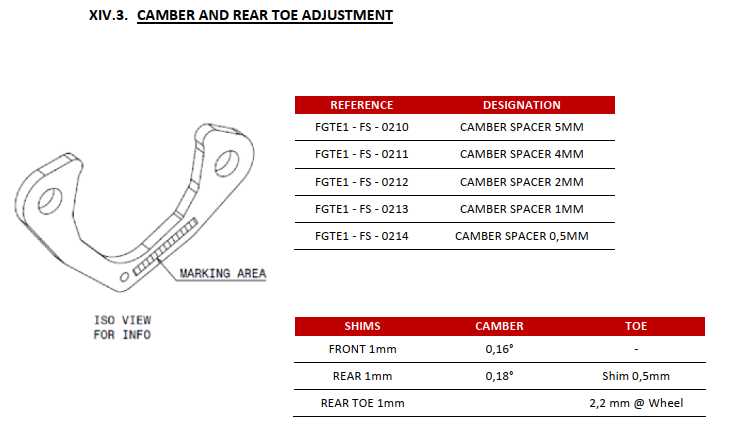
1 degree camber change needs 6.5 mm camber shim. Steering arm compesation = 5 flats = 2.5mm
0.2 degree camber change neeeds 1.3mm camber shim. Sterring arm compesation = 1 flat = 0.5mm
Rear Axle
1 degree camber change needs 6.0 mm camber shim. Toe arm compesation = 2.5mm shim
0.2 degree camber change needs 1.2 mm camber shim. Toe arm compesation = 0.5mm shim
Wet Performance
Wet Checklist
- Headlights & Wiper
- Rain Light On
- Wet Switch On
- Defrost On
- AC On
- Fan On
- Pedal Map 1 (Least aggressive Boost Increase)
- Brake Bias Rearward
- TC 5/5 for damp, 7/7 for wet. By using the “Wet Switch” it already changes to a different software mapping
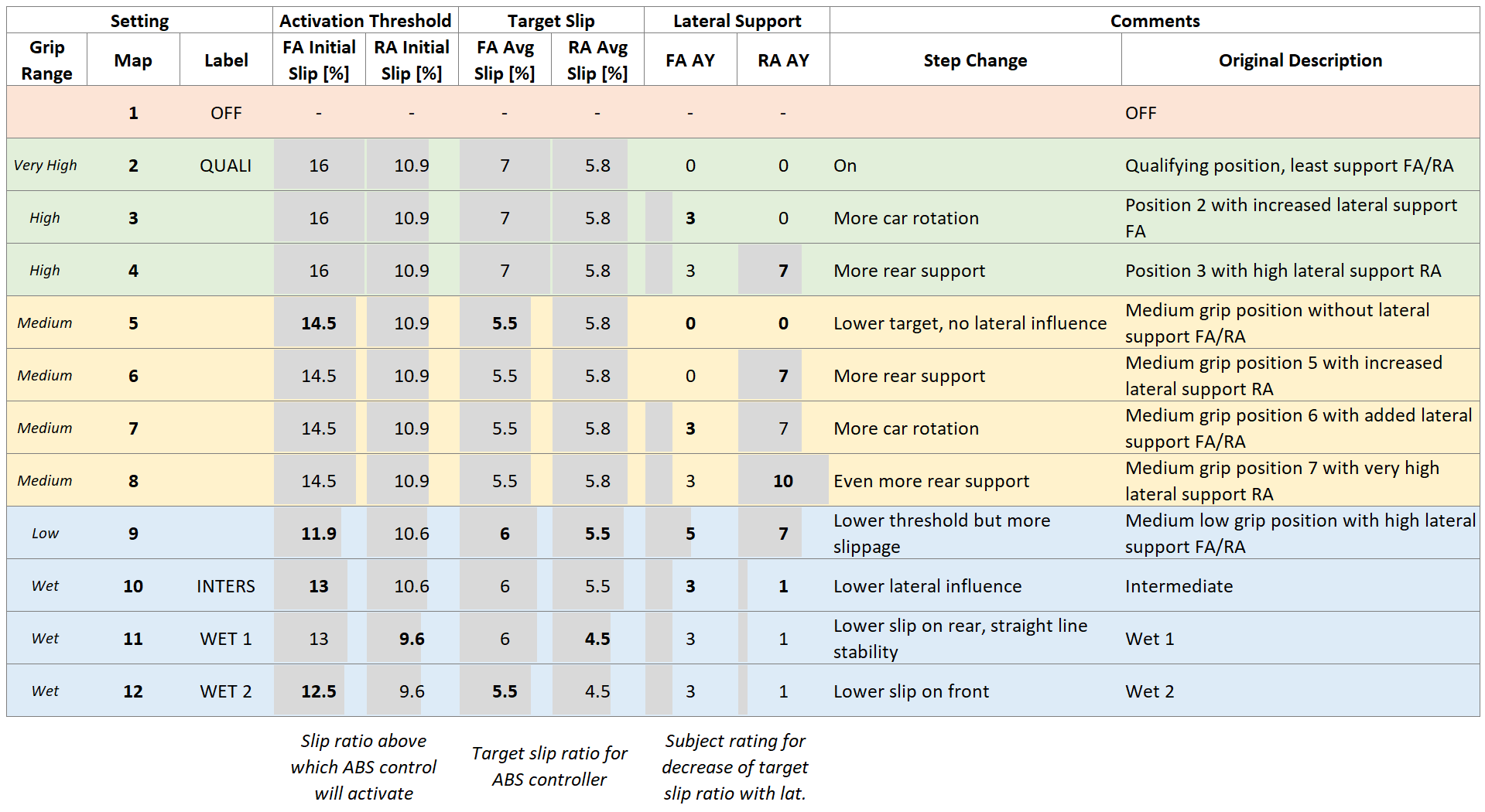
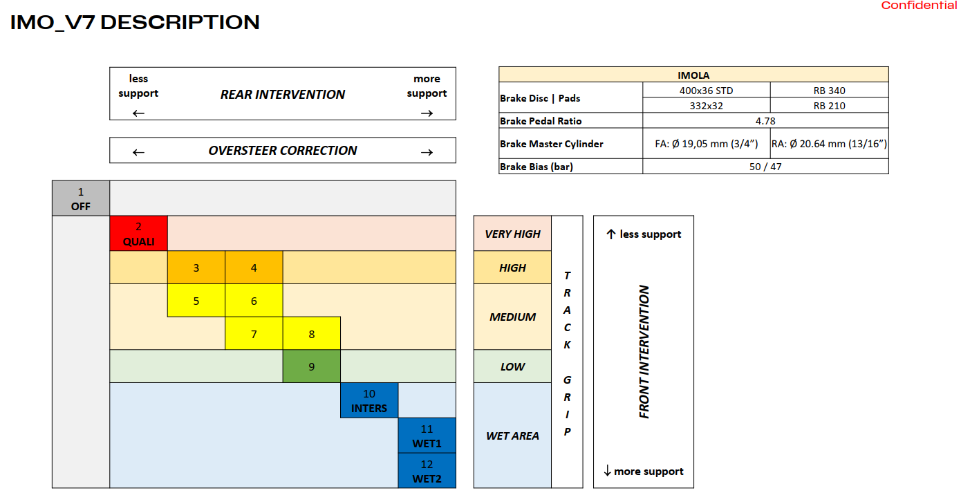
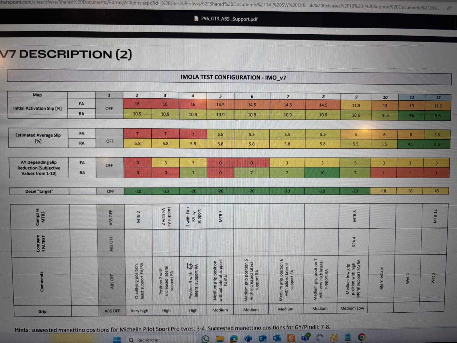
- ABS: 10 for Damp, 11 for Wet
Wet Setup
In R05 - Indianapolis 2024, Onofrio reported very high US in wet conditions during the race. Our hypotesis is that we would need a 2% LLTD change to the rear to re-balance the, but this needs to be verified. We moved the brake bias 1% to the rear with Charlie and it seemed good, but ir needs to be verified.